Slice, mask, and recolor data
Masking lets different spatial or segmented regions of one dataset use independent colors, visibility, and animation.
Choose a slicing method
Microscopy Nodes offers two slicing modes when loading or reloading:
| Mode | Best for | Limitation |
|---|---|---|
| Shader slicing | A clean, movable box slice | One box; the data itself is not masked |
| Geometry slicing | Custom objects, labels, multiple regions, and sparse reloads | The mask is voxelized and can show stair-step artifacts |
Shader slicing is the default. Choose geometry slicing with in the loading panel's On load – Slicing controls when you need the more flexible workflows below.
Use the Slice Cube
The loaded Slice Cube can be moved, rotated, or scaled like any Blender object:
Gmoves it;Rrotates it;Sscales it;- press
X,Y, orZafter a transform to constrain the action to one axis.
With geometry slicing, each channel passes through a Mask Grid node. Its default box mode uses the Slice Cube and provides separate Inside and Outside grid outputs.
Mask with any object
This workflow requires a Mask Grid node in the volume's Geometry Nodes tree. It is added automatically when the dataset is loaded or reloaded with Geometry slicing. If the dataset was loaded with Shader slicing, add a Mask Grid node yourself and connect the channel grid to its Grid input, then connect Inside Mask or Outside Mask to the channel bundle in place of the original grid.
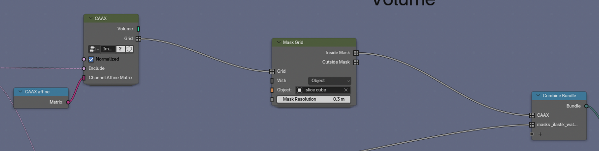
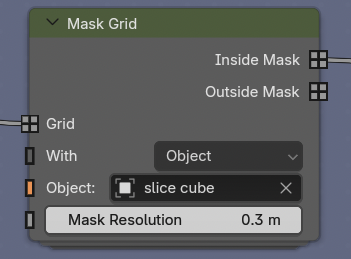
In the Mask Grid node, use With to choose the mask source:
- Object or Collection voxelizes Blender geometry;
- Mesh accepts geometry already available in the node tree;
- Grid accepts an existing mask grid;
- Box uses an object's bounding box, as in the default Slice Cube setup.
Set the corresponding Object, Collection, Mesh, or Mask input. This allows an icosphere, a sculpted mesh, an isosurface, or a segmentation to define the visible region. Inside Mask keeps data inside the source; Outside Mask keeps its complement.
The mask resolution controls how finely Blender voxelizes an object. A finer value follows curved surfaces more closely but requires more computation.
Give regions independent appearances
To color the inside and outside differently:
- Keep one Mask Grid output connected to the original channel.
- Add a second channel to the Geometry Nodes channel bundle.
- Connect the other mask output to that channel.
- Add a matching channel in the shader.
- Give each shader branch its own intensity limits, LUT, alpha, or emission settings.
The channel names in Geometry Nodes and Shader Nodes must match.
Use segmentations without losing intensity
A label mask or generated surface can define a volume mask. The masked region still contains the original intensity values from the source volume, so it can be recolored without replacing the microscopy signal with a flat segmentation surface.
This is particularly useful for dense EM data: show the complete volume in grayscale while highlighting annotated organelles with a separate color map.
Understand mask artifacts
Geometry masks operate at voxel resolution. Curved or rotated boundaries may therefore show voxel-shaped striations, especially at a strongly downsampled scale.
- Increase the mask resolution for a finer boundary.
- Work at a higher data scale when the final result requires it.
- Prefer shader slicing when you only need a clean box cut.
The resulting mask can also define which voxels are loaded at high resolution. Continue with Large datasets and sparse reloading.
When each masked region needs to move independently, continue with Split and animate subvolumes.